Neewer RGB660 WIFI module
Overview
Neewer shipped it's RGB660 lights with bluetooth support, but both the phone app as well as the bluetooth stack on the lights are horrendous. In this guide I will describe how to build a little module that will allow you to reliably control your Neewer RGB660 lights over WIFI.
You can now also buy a fully assembled Neewer RGB660 WIFI module on my Tindie store!
Video: How to connect Neewer RGB660 studio lights to WIFI using a ESP32 module
Introduction
Neewer shipped it's RGB660 lights with bluetooth support, but both the phone app as well as the bluetooth stack on the lights are horrendous. They cannot maintain a stable connection with each other and any attempts to control the lights from any further than directly standing next to them is likely to fail.
One approach to improve this is to use a ESP32 flashed with ESPHome and Aria Burrel's NeewerLight components, located close to the light. However, move the light or the ESP32 to far away from each other and you'll quickly run into connection problems again.
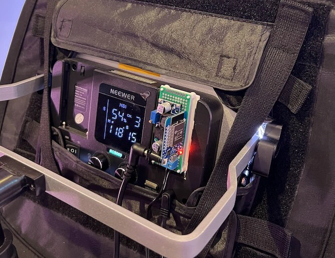
To resolve this problem I came up with the idea of mounting an ESP32 directly to the back of the Neewer RGB660. And for improved ergonomics and convenience I added the option of powering the ESP32 directly from the 15V DC line of the Neewer RGB660. That way the ESP32 providing WIFI connection always lives directly with the Neewer RGB660 and due to it's extreme proximity to the light maintains a reliable and consistent bluetooth connection while functioning as a WIFI bridge and providing seemless integration into Home Assistant or Bitfocus Companion.
Buy a Neewer RGB660 WIFI module
You can now buy a fully assembled Neewer RGB660 WIFI module on my Tindie store.
Tools and Parts
Overall this project is pretty straight forward and is in my eyes a great way to get started with electronics and soldering. That said, it will require a few cheap electronics components, a little bit of soldering as well as a single 3D printed part.
To complete this project you will need:
- 1x ESP32 D1 mini
- 1x LM2596S buck converter
- 1x 2.5x5.5mm right angle barrel plug
- 1x 2.5x5.5mm right angle barrel jack
- 1x 2 pin terminal block
- 1x 3x7cm prototype board
- 1x right angle pitch male header pins
Most of those parts can be easily acquired on Amazon. The links a bove are affiliate links. Note that the accumulated prices for individual parts can quickly add up and buying in bulk is significantly cheaper.
The cheapest and easiest way to get a 2pin terminal block, a 3x7cm prototype board and some right angle pitched male headers are to simply buy a prototype PCB kit.
In addition to a soldering iron, some solder and wire you will also need a pair of side cutters, tweezers, a multimeter and some helping hands. I have just linked the ones I am using, but any eqivalent toolswill do.
You can get the mounting plate from Thingiverse. You can either download the STL and print it yourself or you can use one of the many online 3D printing services.
Assembly
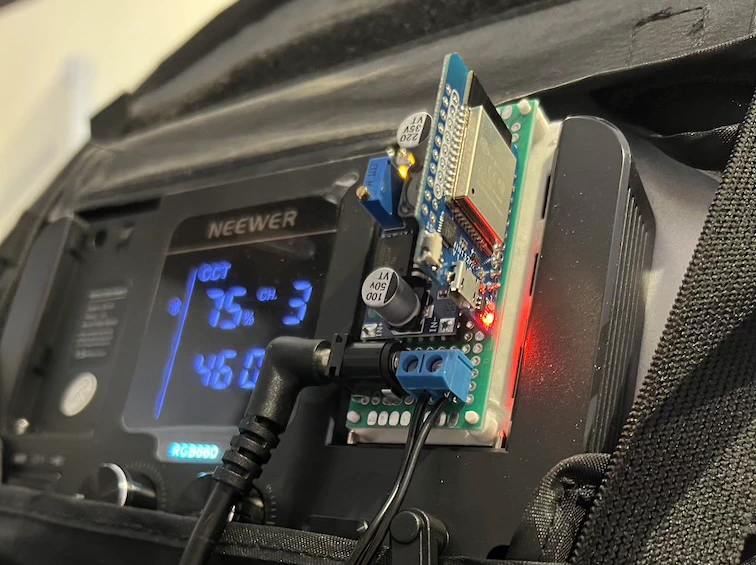
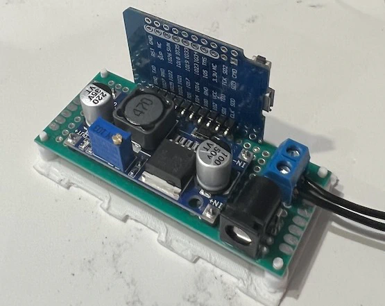
There really only are four components that need to be soldered to the prototype board: the ESP32 D1 mini, the buck converter, the barrel jack and the 2 pin screw terminal.
To attach the D1 mini and the buck converter we'll start by soldering header pins to both of them. Use the angled header pins for the ESP32 so we can mount it upright to the prototype board. It's important that you pin out the G and VCC pins on the D1 mini, so solder the header pins to the pin row that has both of these pins. For head dissipation and space, also make sure that the MCU is facing away from the vertical pins. No other pins outside of G and VCC need to be attached.
Next solder 4 regular male header pins to the through holes of the 4 buck converter corners. We will use the other end to attach the buck converter to the prototype board. You should have received some rows of straight header pins with the D1 mini. Use the side cutters to trim 4 individual pins from them for this.
Once the header pins are in place, layout everything on the prototype board. Make sure you can fit the D1 mini, the buck converter, the barrel jack and the terminal block. I recommend having the barrel jack facing off to the left of the board. That way the angled barrel plug of the Neewer RGB660 will sit in a natural position with minimal amount of strain. How exactly you place the other components is not really critical as long as you can fit everything onto the board.
It is now time to solder the components onto the prototype board. Bending some of the pins over on the back of the prototype board will help keep the through hole components in place while you solder them up. For now just make sure to fill each of the holes in the prototype board that has pins coming through it with some solder to keep all the components in place. We will focus on wiring everything up next.
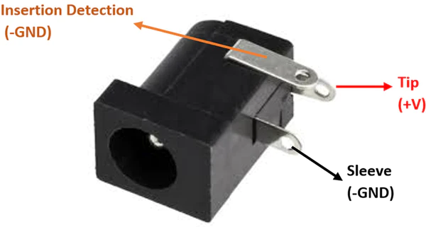
Wiring up the components is super straight forward. The biggest challenge here is to figure out which pins of the barrel jack and which cable of the barrel plug are the sleeve and which the tip.
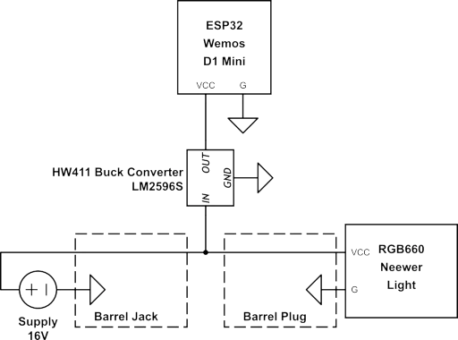
For the barrel plug a multimeter is probably your best bet. Just check for continuity between the end of the cables and the barrel sleeve/tip. The barrel jack layout is standardized and the pin closest to the jack is the sleeve and the pin furthest away from the jack is the pin. Wire both the jack sleeve and tip pins to one of the terminal block pins each. Then attach the plug wire ends, such that the plug sleeve wire connects to the barrel sleeve pin and the plug tip wire connects to the barrel tip pin. This will make sure we are just fowarding the 16V through to the light.
Now hook up the buck converters IN- pin to the sleeve wire run and the IN+ pin to the tip wire run. Before wiring up the ESP32 we will now need to adjust the buck converter voltage. Plug in the Neewer RGB660 power supply to the barrel jack and use a multimeter to measure the output voltage between the OUT+ and OUT- pins of the buck coonverter. Turn the little screw on the buck converter counter clockwise until you see the voltage start dropping. Stop at 5V.
Unplug the power brick again and solder up the buck converters OUT+ and OUT- to the D1 mini's VCC and G pin respectively. Plugging in the power brick again should now power up your ESP32. And if you did something wrong you will now find out.
Firmware
To install the firmware and get your Neewer RGB660 WIFI module setup, please checkout the Neewer RGB660 WIFI module documentation.
Installation
In a last final step mount the prototype board onto the 3D printed mounting tray and slide the tray into the battery mount on the back of Neewer RGB660. You can now plug everything in and enjoy your new WIFI enabled Neewer RGB660. Congratulations!